Adding a EXP810 to an existing DS4700

More information: ftp://ftp.software.ibm.com/systems/support/system_x_pdf/59y7287.pdf

Connecting storage expansion enclosures at the end (bottom) of a drive loop 

To add a 16-drive expansion enclosure, for example, an EXP810 or EXP420 to the DS4000 subsystem configuration, you basically follow the same procedure as in adding the 14-drive enclosure to a DS4000 subsystem configuration; however, the port connections on the 16-drive enclosure are different, as illustrated in Figure 4and the three steps that follow it.

1. Insert the small form-factor pluggables (SFPs) or gigabit interface converters (GBICs) into only those ports that you intend to use. Do not leave GBICs or SFPs inserted into port connectors without connecting them to other ports using cables.
2. Extend one of the drive loops (that is, drive loop A) in a DS4000 storage subsystem redundant drive loop pair by connecting the OUT port of the last storage expansion enclosure to the IN port of the storage expansion enclosure as shown in Figure 1Note: The port name on an EXP810 is not labeled IN. See Figure 4 for details.

Attention: Carefully reconfigure only one drive loop at a time, making sure that the drive loop that you modify is correctly connected and in Optimal state before you attempt to reconfigure another drive loop. Take this precaution to prevent the arrays from being inadvertently failed by the DS4000 storage subsystem controllers, which happens when two or more drives in the arrays cannot be reached through either drive loop in the redundant drive loop pair.

3. Power on the added storage expansion enclosure unit.
4. Wait a few seconds; verify that the port bypass LEDs of all of the ports in drive loop A, now extended to the storage expansion enclosure, are not lit. Using the DS Storage Manager Client Subsystem Management window, verify that the storage expansion enclosure is added and displayed in the Logical/Physical view of the window.Correct any errors before you proceed to step 5. For port bypass, complete the following steps:

  1. Make sure that the SFPs and GBICs or fiber cables are in good condition.
  2. Remove and reinsert SFPs, GBICs, and fiber cables.
  3. Make sure the drive expansion enclosure speed switch is set to the same speed as the existing drive expansion enclosures and the DS4000 storage subsystem speed setting.
  4. Make sure that the ESM is functioning correctly by removing and swapping it with the other ESM in the same drive expansion enclosure. For enclosure ID conflict, set the drive expansion enclosure ID switch to values that are unique from the current settings in the existing drive expansion enclosures and storage server.


Call IBM support for assistance, if the problem remains.

5. In the other drive loop (drive loop B) in a DS4000 storage subsystem redundant drive loop pair, remove the connection from the storage subsystem drive loop port to the OUT port of the last storage expansion enclosure and connect it to the OUT port of the drive enclosure as shown in Figure 2.Note: The port name on an EXP810 is not labeled OUT. See Figure 4 for details.
6. Wait a few seconds; verify that the port bypass LEDs of the two ports in the connection between the storage subsystem drive loop port and the OUT port of the drive enclosure are not lit. Using the DS Storage Manager Client Subsystem Management window, verify that the drive enclosure does not indicate the Drive enclosure lost redundancy path error. See step 4 for possible corrective actions, as needed.Note: The existing storage expansion enclosures are shown with “Drive enclosure lost redundancy” path errors until you establish the Fibre Channel cabling connection that is described in step 7.
7. In drive loop B, cable the drive enclosure IN port to the OUT port of the last enclosure in the already functioning storage expansion enclosure drive loop, as shown in Figure 3.
8. Wait a few seconds; verify that the port bypass LEDs of all of the ports in drive loop B to which you have added a connection are not lit. Using the DS Storage Manager Client Subsystem Management window, verify that all of the drive enclosures in the DS4000 redundant drive loop pair to which the enclosure was added do not report the “Drive enclosure lost redundancy” path error.


Figure 1: Cabling a single drive enclosure to the end of a functioning drive loop (step 1 of 3)

Figure 2: Cabling a single drive enclosure to the end of a functioning drive loop (step 2 of 3)


Figure 3: Cabling a single drive enclosure to the end of a functioning drive loop (step 3 of 3)


Figure 4: Cabling an EXP810 to the end of a functioning drive loop

Connect Powervault 220s to a server

Cabling Your System for Joined-Bus, Split-Bus, or Cluster Mode

How you cable your storage system to your host system(s) depends on the bus configuration you choose: joined-bus, split-bus, or cluster.

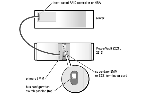
  • A joined-bus configuration is one in which two SCSI buses are joined to form one contiguous bus.
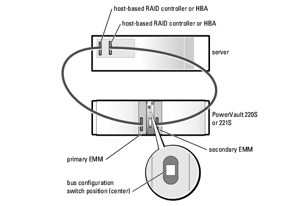
  • A split-bus configuration enables you to connect your storage system to either one server with a multichannel RAID controller, or to two servers. However, if one server fails, information controlled by that server is inaccessible.
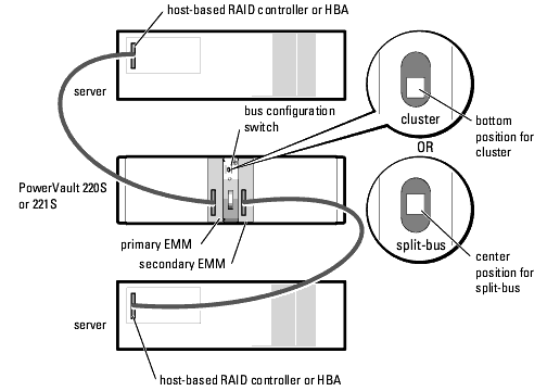
  • A cluster configuration offers multiple paths to the system, which provides high data availability.

Joined-Bus Configuration


Split-Bus Configuration (One Server)

Cluster Configuration or Split-Bus Configuration (Two Servers)

SCSI ID Assignments

Configuration Cables
Used
SCSI IDs Used
15 14 13 12 11 10 9 8 7 6 5 4 3 2 1 0
Joined-bus 1                 H S            
Split-bus—primary EMM 1                 H S            
Split-bus—secondary EMM 1                 H S            
Cluster 2 S               H H            
NOTE: The unshaded SCSI IDs are available for hard-drive use as indicated for each configuration. The reserved SCSI IDs are used as follows:
H = used by the host system initiator.
S = used by the storage system SES.

SCSI ID Numbers and Associated Hard Drives 


Split-Bus Module Modes

Mode LED Icon Position of Bus Configuration Switch Function
Joined-bus mode  


Top LVD termination on the split-bus module is disabled, electrically joining the two SCSI buses to form one contiguous bus. In this mode, neither the split-bus nor the cluster LED indicators on the front of the system are illuminated.
Split-bus mode  


Center LVD termination on the split-bus module is enabled and the two buses are electrically isolated, resulting in two seven-drive SCSI buses. The split-bus LED indicator on the front of the system is illuminated while the system is in split-bus mode.
Cluster mode  


Bottom LVD termination is disabled and the buses are electrically joined. The cluster LED on the front of the system is illuminated while the system is in cluster mode.
More information:

Extend boot volume on Windows Server 2000/2003

source

Before you begin, make sure that you do not have an active snapshot on the VM, extending a virtual disk with a snapshot will cause corrpution

Extend the boot volume of Windows Server 2003 Virtual Machine
To start, I have a Windows Server 2003 Virtual Machine that has a 5.3G disk allocated to it, I need to expand this disk to 10G.

1

Step 1: Power off the virtual machine that holds the boot volume that you want to extend.

Step 2: Make a backup copy of your virutal disk, this is optional but if you mess up don’t call me unless you’re willing to pay.

Step 3: From the service console, increase the size of the .dsk or .vmdk virtual disk file. This can also be accomplished through the Virtual Infrastructure Client if you are using VirtualCenter 2.x+.

[root@esx-test local]# ls -lah test.vmdk

-rw------- 1 root root 5.4G Jul 18 13:57 test.vmdk

Extend the virtual disk with vmkfstools. The input to the -X switch is the size that you want the disk file to be not the size you want to extend the disk file by.

[root@esx-test local]# vmkfstools -X 10G test.vmdk

View the new size of test.vmdk

[root@esx-test local]# ls -lah test.vmdk

-rw-------    1 root     root          10G Jul 18 13:57 test.vmdk

Step 4: For this step you will need an additional Virtual Machine running Windows Server 2003. Power off the second Virtual Machine, and add the disk from the first Virtual Machine to it through the mui. Power up the second Virtual Machine and verify that the imported disk has unallocated space on it.

 2

From the run menu type “diskpart.exe” to enter the command line utility to resize disk partitions in Windows Server 2003.

 3

The command list volume will show you all the available volumes. Select your volume as shown below. select volume 1 corresponds to the “D” volume that I want to exntend. Finally extend the volume with the extend command.

4

If all goes well, the partition will be immediately exnteded under the Disk Management snap in.

5

Step 5: Shut down the second Virtual Machine and remove the disk from the second Virtual Machine. Power on the first Virtual Machine and check out your new space.

 6

Adding a physical disk to LVM in Redhat/CentOS

Source

Problem:

My computer only has 20GB of disk space. I just have 1 partition. I want to add another disk (40GB). I don’t want to add another partition (and I really don’t want to reinstall the whole system), I want to increase the size of the root partition to 60GB. i.e. I want the root partition to span across two physical disks.

Solution:

  1. Add new physical disk. Boot.
  2. # pvscan 

    This will show you the current physical volumes.

  3. # fdisk /dev/sdb 

    Add the disk to your machine as a primary partition. Partition type: “8e (LVM)”. Obviously /dev/sdb may be different on your system.

  4. # pvcreate /dev/sdb1 

    This creates a new physical LVM volume on our new disk.

  5. # vgextend VolGroup00 /dev/sdb1 

    Add our new physical volume to the volume group: VolGroup00. Again, this group name may by different for you, but this is what Redhat & CentOS assigns by default when you install your system.

  6. # pvscan 

    You should see the new physical volume assigned to VolGroup00.

  7. # lvextend -L+40G /dev/VolGroup00/LogVol00 

    This increases the size of the logical volume our root partition resides in. Change the -L flag as appropriate.

We’ve just added 40GB to the logical volume used by the root partition. Sweet as. Now we need to resize the file system to utilize the additional space.

  1. Reboot into rescue mode using your CentOS CDROM. 

    From memory this involves typing linux rescue as your boot option.

  2. When prompted, skip the mounting of system partitions.
  3. # lvm vgchange -a y 

    This command makes your LVM volumes accessible.

  4. # e2fsck -f /dev/VolGroup00/LogVol00 

    Run a file system check, the -f flag seems necessary. No idea what we do if the returns an error?

  5. # resize2fs /dev/VolGroup00/LogVol00 

    Without any parameters resize2fs will just increase the file system to the max space available.

Reboot and your root partition is now 40GB lager, spanning multiple disks.